Flag Pole Manufacturers and Companies

Flagpole Manufacturers and Companies

Here is just a small list of the many companies out in the USA that sell factory made flagpoles. I did an Internet search and came up with no less than 50 companies. I think you will find that there are probably less than 10 actual flagpole manufacturers and that many companies that sell poles actually are selling the same product. Be sure to find out WHO actually makes the pole.

Pay attention to sidewall thickness. This is a measurement of the amount of metal that is in the pole. More metal usually means greater strength. Also ask about stainless steel hardware. You want metal that absolutely will not rust. The halyard and the trucks are also very important. Price is almost always a good barometer of quality. High quality components simply cost more money.

SunSetter Products
This company makes a unique pole that telescopes up to a height of 20 feet. It has no ropes since you raise and lower the flag by simply clicking the pole up and down. This is worth a look.

Quinn Flags & Banners
This company has a full line of aluminum and fiberglass flagpoles in any size you want. They also have a fantastic selection of historical US flags. I am getting ready to buy one of the First Navy Jack flags that has a serpent with the words "Don't Tread on Me".

Concord Industries, Inc.
This company has a full line of great aluminum flagpoles. But they do not sell direct. You must deal with one of their distributors.Visit their website to find out who sells them in your area.

Hennessy House
This is a very unique company. They make historical wooden flagpoles! If you want to keep your colonial home totally authentic, then you might want to contact these folks. I found other companies that make wooden poles while I was doing my search so if you want comparative pricing, be sure to do an extensive web search.

American Flagpoles & Flags
This company has a wide variety of flagpoles and flags. They have a neat telescoping aluminum pole. These telescoping poles are the latest in flagpole technology. If you have one of these you can easily take down your flagpole if you need to for any reason. Traditional poles, once set, are pretty tough to take down.

Related Column: Flagpole Tips

Column B381

Closet Organizers

Closet Organizers - Cubbie Closet Storage Plans

Closets, at least in my house, are the black holes that capture anything and everything. In just a matter of weeks or months there can be a big mess just behind the bulging door. To compound the matter, myself and many of my family members are pack rats. I contracted the disease from my mother, bless her heart! But I have started to solve the problem at my home the way I did it for years for some of my customers: simple closet organizers made from scrap plywood.

Factory Made Systems

You don't have to go to all the trouble to build your own setup if you don't want to. There are all sorts of companies that fabricate closet organizers and you can even buy factory made ones at most of the home centers and larger chain retailers. But the trouble with factory made units is that you get what they build and design. If you want custom sizing, you need to do it yourself or go with a local fabricator. Fabricated units made with melamine or laminate covered particle board can be very expensive. The price of larger setups may take your breath away.

Layout Tricks

Looking at the simple plan, the cut sheet requirements and the photos that are part of this bulletin will give you an idea of how to build this unit. The method I prefer to use incorporates mortise joints or grooves that can be found on some of the different parts. These mortise joints align the shelves and vertical dividers. They also make for solid connections between the parts so that you don't have to rely on mechanical fasteners such as nails or screws. The trouble is, it takes a router and a little layout skill to create these grooves. In fact, it is the most difficult part of the job. You don't have to do it, but it does aid, to some degree, the assembly of the closet cubbie system.

The trick to getting the grooves in all the correct places on the dividers is to make the marks at the same time on all of them. You can lay different dividers next to one another so that the two interior surfaces that face each other are aligned just like two pages in a book. When you open a book and lay it on a table the pages are flat but once the book closes they face one another.

Some Critical Measurements

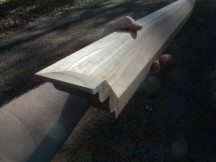
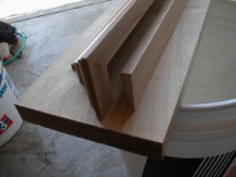
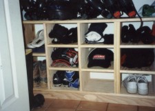
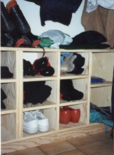
I used 3/4 inch thick plywood to make my cubbies. One of the reasons is that I like to create a 1/4 inch deep mortise groove. If I were to use just 1/2 inch thick plywood for my system this would cause huge problems when two grooves would be next to one another. There are several places where this happens. Look at the photos and see how several shelves are at the same level and they both connect to one vertical divider. You can use thinner wood and go with a more shallow mortise say 1/8 of an inch, but that is often impractical.

Knowing that you are going to have a 1/4 inch deep groove, you need to always keep this in mind as you measure. As I have noted in the Cut List, not all vertical dividers are the same length. The inner dividers are 1/2 inch longer than the end ones because they extend 1/4 inch into the top and bottom shelf.

Router Layout

I used a hand held router to create my mortises. You can buy a 3/4 inch wide router bit. A 1/4 inch deep groove can be made in one pass with the router. To keep the lines straight, I clamp a framing square to the wood piece and glide the router along the framing square edge. It works perfectly. The trick is to determine the offset. My router starts the cut 2.5 inches away from the outer ring of the router. Yours will be different! Do a test on a scrap piece of lumber to determine the offset.

Closet Cubbie Cut List

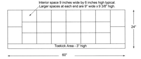
Below are the dimensions of some of the pieces I used to build my closet cubbie system. Keep in mind that the most critical pieces are actually the vertical dividers. The overall width of the unit will change depending upon your closet! But, you can have some excess space if you like at each end. I built mine so it fit almost perfectly within the total available width of the closet.

If you look at the photos, each inner vertical divider is 20 inches tall. The vertical piece at each end and in the middle where you see the extra wide cap molding are only 19.5 inches tall. Why? Because I wanted the top and bottom to overlap the sides. Keep in mind that I built two units and butted them together. The extra wide cap molding that hides the rough plywood edge hides this joint. So, each cubbie unit of mine has two vertical pieces of each height since there are four vertical pieces per unit. The top and bottom of each unit in my setup were simply 30 inches long. All pieces, including the small shelves, were the same depth -- 11 and 3/4 inches. I made them this size so I could confidently get four 8 foot long pieces of material out of each sheet of plywood.


Assembly

I assembled the units by building the outer shell first. I used three 2 inch long drywall screws at each corner. Remember, the top and bottom overlap the sides. Once the outer box was built I slid the two vertical dividers into position and used small 4d finish nails to hold them in position. The last things that are installed are the small shelves. I actually determined their width only after the unit was built. Since I wanted a tight fit for each shelf, I custom cut each one ONLY after the unit was assembled and I could get a crisp measurement at each shelf location. Precutting these shelves is a mistake in my opinion. It is safe to cut the top, bottom and vertical pieces since they work out. But if you don't have the depth of your mortise router bit just right, you may create a shelf that is too tight or too loose. You don't lose any time by cutting the shelves last.

Closet Cubbie Plans

Front View

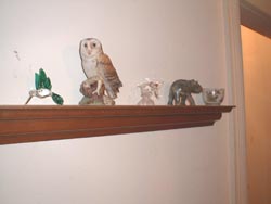
The beauty of this system is that you can make the interior spaces whatever you want. The only two limiting factors are the closet width and the height you wish to go. Keep in mind that I wanted to use the top of my setup as a shelf. Therefore, I kept it about 10 inches below were average coats hang from the closet rod.

Side View

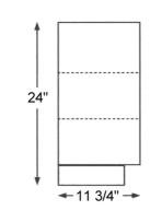
The dashed lines are the horizontal shelves within the unit. I didn't show the dashed line for the shelf at each end that is actually centered between the top and the bottom of the unit.

The toe kick was just made out of scrap plywood. I felt that it would be better if the unit was not just sitting on the floor. I recessed the toe kick in from the front just about two inches. The closet cubbie ;unit just sits on the toe kick and is not permanently attached. The weight of the unit will easily hold the toe kick in place. The toe kick is just 3 inches high.

Related Articles: Shoe Storage, Adding Closet Storage Space, Two Closet Plans - Materials, Two Closet Plans - Build

Column B388

Use Crown Molding to Make Decorative Shelves

Crown molding is a popular building material. Trust me, I know! Perhaps the most common use of the material is at the intersection of a wall and a ceiling. Crown molding really adds a nice touch to a room or hallway.

But this molding can also be used to create a nice decorative shelf to display trinkets, plates and other knickknacks. To easily accomplish this task you need a few special saws and a few hours of time.

Photo Essay

I say we get started building one of these shelves. The first thing to realize is how the crown molding fits in a miter saw in order to produce the correct mitered cuts. Look at Photo 1. The crown molding is actually upside down in the photo. This is correct.

.

Photo 1

Photo 1

Why? The molding needs to be positioned in the saw the way it will sit on the wall. The table and fence of the saw simulate the 90 degree intersection of a typical wall and ceiling. The vertical saw fence is the wall and the flat saw table is the ceiling. Since the simulation is upside down you must hold the molding this way.
.

Photo 2

Photo 2

You cut your shelf so that the longest points of the shelf are the top of the molding. Look at Photo 4 to see an exploded view of a corner of the shelf. The molding is oriented top side up in this photo and you can see the small return piece that makes up the finished corner.
.

Photo 3

Photo 3

How do you cut that small triangular corner piece? Simple. You cut the crown molding as if you were going to run it around an outside corner in a room. But in this case you have to clip the small piece. Look at Photos 2 and 3. I have cut the miter for the return piece and now I have flipped the molding so it lies flat on the saw table. It is OK to do this for the final cut.
.

Photo 4

Photo 4

The saw cut in Photo 3 just kisses the intersection of the angled face and the back of the foot of the molding. If you cut past this intersection, then the small triangle piece will be too long. Cut into the angled face and you will have a gap. Cut a trial piece and you will see exactly what I mean when you dry fit the corner to the main piece of crown molding that makes the front of the shelf.
.

Photo 5

Photo 5

The Flat Top - Once you have assembled the two corners to the main piece of crown, you should have a semi-completed shelf similar to what you see in Photo 5. Note how the small triangle piece, once glued and nailed, is flush with the back foot of the main run.

Your challenge at this point is to simply cut a piece of wood that will fill the void at the top of the crown molding. Look at Photo 6 to see what I mean. I have cut the piece and have held it out so you see that it can drop into the crown molding to make a flat top surface.

It just so happened that my molding had a 45 degree angle to the rear sloping face. This made it easy to cut my top shelf. I simply set my table saw blade at 45 degrees and cut the top rear shelf. The sides of this piece also get clipped at a 45 degree angle.

.

Photo 6

Photo 6

This top rear piece gets glued and nailed to the back of the crown molding. You can use small brad nails.
.

Photo 7

Photo 7

The final piece of the shelf is a small cleat that gets attached to the wall. This piece of wood might also have to have an angle cut depending upon the size of the molding you use. In my case I had to cut my wall cleat at a 45 degree angle. I nailed this to the wall and then set my shelf on top of it. Small screws were used to go down through the top rear shelf piece into the wall cleat. You can see the finished shelf in Photo 7.

If you REALLY want to discover how to install Crown Molding, you need my Crown Molding eBook or Installing Crown Molding DVD..

Column B399

Pre-Finished Crown Molding

Pre-Finished Crown Moldings

I used a pre-finished crown molding for a decorative shelf. These are often available at traditional lumberyards, hardware stores and home centers. If you want to see some superb crown moldings with very different profiles, then visit a kitchen cabinet store. Sounds crazy, but they have many exquisite prefinished crown moldings that are used to finish off the tops of cabinets.

The crown molding I used happened to be part of an entertainment center in my basement. The cabinets were made by Merrillat - a major manufacturer of kitchen, bath, home office and home entertainment cabinetry.

In fact, the molding I used has a space for an accent molding. Once the crown molding is in place, there is a small vertical face. Merrillat makes a small twisted rope molding that fits perfectly in this space. After it is added, the molding looks as if it might have been hand carved. Hunting around for moldings such as this makes all the difference in the world

Column B399

Custom Crown Molding

Custom Crown Moldings

If you want a really special look, why not have your own crown molding made? If you live in a sizable city or town it is usually quite easy to find a woodworking mill that will make any crown molding you can draw.

If you can't find a woodworking mill, you might find a woodworker who has equipment that can make moldings. The trick to finding woodworkers is to visit fine lumberyards where these folks buy their raw materials.

The woodworking mill or individual woodworker use basically the same tools. But the woodworking mills almost always have better equipment, large capacity and the ability to grind cutting knives in a short period of time.

The best part is that the woodworking mills often save the sharp steel knives used to cut the profiles. An older mill might have 100 or more knives in stock that they can use to create a truly custom look. All you have to do is ask to see the different profiles they have already produced.

If you want to have your own personal style, you need to consult with them so they can help you draw a profile that will be easy to cut. It is possible to copy different elements from several crown moldings and combine them into one new profile. Simply use your imagination and start to draw. It helps to have small sample lengths of existing crown molding handy. You can trace the profiles on a piece of paper.

Column B399

House Settling Cracks Information

Literature for Settlement, Shrinkage and Foundation Problems

There are lots and lots of books out there about foundation settlement, cracks, expansive clay soils and lumber shrinkage. Most of them are somewhat technical. If you live in a town that has an engineering college or school, this is the place to start. Libraries will very likely have these books as well if they have a strong science section.

If you do have a college or university in your area, it is always a good idea to call and see if you can find a professor who is willing to talk to you. Most are very nice people who have an affection for books! This works to your advantage.

Two Winner Books

In talking with several structural engineers in my own town, both of them pointed me to a swell book about residential foundation problems. One of the engineers, Bob Becker P.E. said, "It is the Bible of the engineering industry."

The particular book is titled Foundation Repair Manual (McGraw-Hill Portable Engineering). It was authored by Robert Wade Brown. Mr. Brown's book is simply the best. Find a copy and read certain chapters if you have foundation problems. Some chapters are way over my head, but most are readable.

Book cover

The other book you should look at deals with cracks caused by lumber shrinkage. It is titled Design of Wood Structures - ASD by Donald E. Breyer. It is also a McGraw-Hill book. This book is heavy into mathematics, but it tells you all about lumber shrinkage! Even at the steep price, it is a solid investment. Just one or two chapters of this book will possibly save you hundreds of dollars in consultant fees whose advice may lead you astray!

Column B288

Wet Bar – Plans and Construction Tips

Certainly you have sat or stood at someone's basement or family room bar and wondered about having one for yourself. As you might imagine, I have built many bars over the years for customers. In fact I remodeled real bars in drinking establishments! Finally, I have one of my own!

Simple Job

Building a wet bar is fairly simple. The tough part of the job is selecting finish materials. There are just so many possibilities! I happened to select cherry wainscoting for the front of my wet bar. This product matched perfectly some wonderful cherry Merrilat cabinets that I have in the same room. The wainscoting was supplied by New England Classic. This is a wonderful company that has all sorts of natural wood and paint grade wainscoting that is custom designed for your personal application or job. You simply send them the dimensions of what you want to do and they come up with a design using their standard parts.

A wet bar wall needs to support a top and shelves that might be on the bartender side. It is not a big deal. The biggest hazard or challenge is offsetting the possibility of tipping the bar over. A U-shaped bar is obviously the best design. A curved wall is also very strong but presents all sorts of challenges to build. My L-shaped bar with a short wing wall turned out to be very stable.

Critical Dimensions

The finished height of a bar should be 42 inches. Try not to deviate from this too much. The front overhang for the patron side of the bar should be 12 inches if you intend to have bar stools. If it is just a standing only bar, a 6 or 9 inch overhang will work fine.

The overhang for the bartender side is a function of your overall design. But keep in mind the rotational force of the bar top if it is a heavy stone product! If the top is not balanced to a large degree, it can exert a force on its own that would make the bar want to lean or tip over. I centered my top on the bar wall for the most part.

Wall Thickness

If you can afford the space, construct the bar wall from 2x6's or better yet 2x8's. I had to use 2x4's because of space problems at my home. The wider the wall the more stability you produce.

Electrical Needs

Don't forget to plan for electrical appliances, mixers, refrigerators, phones, etc. Make sure you have outlets at the right places for anything you intend to have behind the bar.

Lighting

Indirect lighting, hanging fixtures, recessed lights, etc. are all possibilities. Creative lighting can really enhance a wet bar. Visit a true lighting showroom, not a big box store, and get some suggestions from the salespeople. I'll bet they can give you plenty of ideas!

Granite Tops

I love natural stone! My granite bar top gets all sorts of compliments. It is a deep green granite with large quartz crystals. There is a hint of blue in my top as well. Dark granites are easy to care for. If you decide to go with granite you MUST meet with the granite fabricator before you build your walls! The granite supplier will tell you how he intends to mount the top and what the rough height of the wall should be.

In my case, I had to attach a special 3/16 inch thick solid steel plate to the top of my wall. This steel plate was screwed to the wall and the granite was epoxied to the steel. The advantage of the steel is that it supports the stone and makes it virtually impossible for the stone to crack as people lean against it. I have thick granite, but you never know how many high school football players might lean against the edge of the bar or foolishly sit on the edge! You must plan for these crazy events.

wet bar

Column B410

Precast Concrete Walls

Precast concrete technology is undergoing an explosion in growth. It has been used in commercial and industrial construction for years and has now entered the residential market. I can assure you that in many respects, it is the ideal way to build. There are simply too many things that can and do go wrong in the field when you build a foundation on-site using conventional block or even poured walls.

Square, Plumb & Level

Most conventional poured concrete or block foundations are NOT square, plumb, and level. The reasons are numerous. Precast concrete foundations, by their very nature, should come out nearly perfect each time. The panels are poured in square and level template forms in a controlled factory environment. If the foundation designer has all of the dimensions right so the foundation is a perfect rectangle or square, and the builder in the factory follows the designer's plan, then assembling the finished product at the jobsite is like using the fashionable children's toy Lego™ blocks. The only challenge at the jobsite is getting the compacted gravel base level. That is so easy to do with today's laser levels, that it is no wonder a complete foundation can be set in just one day.

Energy Efficiency

When I first saw a precast poured foundation wall, I was amazed at how well it was designed to incorporate energy efficiency. All of the systems include closed cell foam insulation panels on the inside of the foundation. These are poured into the concrete. The foundation walls actually have concrete ribs or studs every 2 feet or so. These cavities between the ribs can be filled with additional fiberglass batts once any plumbing, electrical or other mechanical systems are in place. Your foundation will not waste much energy, that is a fact!

Vertical Steel

These new precast systems are heavily reinforced with steel rods. Steel has enormous tensile strength. The steel that is in a foundation allows the foundation to resist the formation of large cracks that can result from soil pressures on the side of the walls, and poor soil conditions under a wall.

Unfortunately, many traditional poured concrete foundations have no vertical steel rods. Most foundations simply have four rods running horizontally in a continuous manner around the foundation. Two of these are near the bottom of the wall and the other two are near the top of the wall. Horizontal steel bars help to minimize cracks that can develop from poor soil beneath a footer and a wall. They do little or nothing to prevent cracks that can form from soil pressures on the side of a concrete wall. After all, a backfilled basement wall is simply a retaining wall, right? Vertical steel should be used in all poured basement walls. It is standard equipment in the precast systems.

No Footer - Strange but True

Traditional cast concrete footers spread out the concentrated loads of the house onto the soil. The problem is that if stressed, they can and will crack. Most footers are not poured 10 to 12 inches thick. This is the thickness, in my opinion, necessary to provide additional support in poor soil conditions. The actual primary purpose of most traditional 6 or 8 inch thick concrete footers is to provide a level working surface for the foundation panel crew or concrete block masons.

The compacted crushed gravel that is used beneath precast walls will transfer concentrated house loads to high quality, strong soil. If you are building on fill dirt or have poor soil conditions, you need to involve a soils engineer and a structural engineer in your foundation planning. Don't get cheap on me during this aspect of your job.

Limited Availability

The residential precast concrete foundation business is in its infancy. It may not be available in your area. If it isn't are you in luck! Here is a perfect business opportunity for you. Seriously, look at the different companies and see if it isn't time for you to make a career change.

Companion Articles: Precast Concrete Foundation Walls, Precast Concrete Foundation Companies, Precast Foundation Wall Illustrations

Column B266

Wet Bar Photos

Wet Bar Photos

The two photos on this page pretty much tell the tale. Basically, my wet bar consists of two work surfaces. The actual wet bar is behind the serving bar where guests will sit and enjoy a drink or two. The serving bar is basically L shaped, but it has a small return leg that you can clearly see in the first photo. This leg is vitally important to the overall stability of the bar. Without this short wall a person standing or leaning at the end of the bar could easily push/pull the end of the bar to the floor. The little wall is covered with 3/4 inch plywood just below the cherry wainscoting. The plywood is screwed to the 2x4 framing. The bottom plate of the little wall as well as all others, are anchored to the floor with 1/2 inch diameter stud bolts. These things are enormously strong. They have a nut and washer and the tighter you crank the nut, the tighter the plate is pressed to the floor.

The end wall is important, as it supports the bar.

The end wall is important, as it supports the bar.

The actual dimensions of the bar walls were determined by the cherry wainscoting. I wanted the vertical stiles at the ends of the walls to be the exact width of the stiles in the field that you see between each raised panel. So I ordered the wainscoting and took delivery of it before I built the walls. I dry fit the wainscoting on the floor to see just how it went together and what the true dimensions of the system would be once assembled. As you might imagine, it looks superb since the pieces of wood are perfectly balanced. You can do the same thing with many other building materials.

The wet bar has an undermount stainless steel sink. The tops are Brazilian granite - Verde Peacock.

Granite backsplach and counter add a gorgeous touch.

Granite backsplach and counter add a gorgeous touch.

Column B410

Precast Concrete Foundation Companies

poured foundation

Here's a traditional cast-in-place concrete foundation. I watched them build it. It took four days total to set the footing forms, pour them, set the wall panels, pour the wall panels and remove the forms. A precast foundation system would have taken one day at the job site to erect. Wow! Copyright 2018 Tim Carter

Precast concrete foundations are made in controlled conditions inside a building. Most precast concrete foundations can be set in one day.

Precast Concrete Foundation Companies

There are two main companies that make and license their precast systems. Be sure to check out how close each manufacturing plant is to your job site. Transportation of the precast panels can be a significant cost and the greater the distance from your future home to the place the panels are made will impact what you pay.

They are:


I visited the Thermal-Krete website to locate a list of their licensed plants at the time I created this document. I had no luck. They say at the bottom of their website home page:

"Kistner Concrete Product Inc. operates four NPCA nationally certified manufacturing facilities." However, they don't provide an easy link as to the location of these mysterious plants.

I filled out their contact form on March 31, 2018 to see if they respond. Here's a screenshot of my request:

Thermal Krete Form

If they respond, I'll be sure to put up a list of their plant locations for you.

Superior Walls Precast Foundation USA Map

This is a map taken from the Superior Walls website on March 31, 2018. Look at the legend at the top of the graphic so you understand the colors.

superior walls plants

The following is a list of licensed companies who use the Superior Wall's patented technology.

  • Superior Walls by Advanced Concrete Systems
    55 Advanced Lane
    Middleburg, PA 17842
    800-521-3788
  • Superior Walls by Carr-Mitchell Inc
    44 Industrial Drive
    Cadiz, KY 42211
    877-522-9255
  • Superior Walls of Central Virginia
    10101 Superior Way
    Amelia, VA 23002
    866-350-9255
  • Superior Walls by Collier Foundation Systems
    1500 Ellsworth Avenue
    Suite 210
    Heidelberg, PA 15106
    888-817-5537
  • Superior Walls of East Tennessee
    10146 Sparta Highway
    Rock Island, TN 38581
    877-836-9255
  • Superior Walls of Eastern Iowa
    2395 Tech Drive  #9
    Bettendorf, IA 52722
    866-560-9255
  • Superior Walls of the Great Lakes
    4555 134th Avenue
    Hamilton, MI 49419
    800-486-2932
  • Superior Walls of Greater Atlanta
    703A Corinth Road
    Newnan, GA 30263
    866-538-9255
  • Superior Walls of the Hudson Valley
    68 Violet Avenue
    Poughkeepsie, NY 12601
    800-639-4033
  • Superior Walls by Jointa Lime
    1762 Central Avenue
    Suite 301
    Albany, NY 12205
  • Superior Walls of New Jersey
    92 Reese Road
    Millville, NJ 08332
    866-699-2557
  • Superior Walls of North Carolina
    3570 South Main Street
    Salisbury, NC 28147
    877-896-9255
  • Superior Walls of NW Pennsylvania
    9391 West Main Road
    North East, PA 16428
    888-725-8575
  • Superior Walls By Precast Concrete Solutions
    300 S Martin Luther King Drive
    Springfield, IL 62703
    866-522-8565
  • Superior Walls by Precast Systems
    5877 Bullitt Road
    Greencastle, PA 17225
    866-369-3773
  • Superior Walls by Setwright Precast
    11 Mechanic Falls Road  Ste 5
    Oxford, ME 04270
  • Superior Walls of Upstate New York
    7574 East Main Road
    Lima,NY 14485
    800-273-0127
  • Superior Walls of the TriState
    3425 Grant Drive
    Lebanon, OH 45036
    888-840-9255
  • Superior Walls of the Twin Cities
    580 Schommer Drive
    Hudson, WI 54016
    800-467-8279
  • Superior Walls by Weaver Precast
    824 East Main Street, PO Box 759
    Ephrata, PA 17522
    800-352-8196
  • Superior Walls by Weaver Precast of Florida
    350 Thorpe Road
    Orlando, FL 32824
    800-291-2213
  • Superior Walls by Weaver Precast of South Carolina
    8 Hudson Drive
    Spartanburg, SC 29303
    877-542-1213

Companion Articles: Precast Concrete Foundation Walls, Precast Concrete Walls, Precast Foundation Wall Illustrations

Column B266